11. Input Devices
Reflection
Group Assignment
- ☑ Linked to the group assignment page
- ☑ Documented what you learned form interfacing an input device(s) to microcontroller and how the physical property relates to the measured results
- ☑ Documented your design and fabrication process or linked to the board you made in a previous assignment
- ☑ Explained the programming process/es you used
- ☑ Explained any problems you encountered and how you fixed them
- ☑ Included original design files and source code
- ☑ Included a 'hero shot' of your board
Attached is the link to group assignment
Individual Assignment
What I Learned from Interfacing an Input Device to a Microcontroller
I summarised the important learning to me in table below. another interesting information is that lower baud rate is better for longer distances.
| Command/Function | Description | Usage Tips |
|---|---|---|
| pinMode() | Sets the mode of a pin as INPUT or OUTPUT. | Ensure TRIG pin is set as OUTPUT and ECHO pin as INPUT. |
| delayMicroseconds() | Pauses the program for the specified number of microseconds. | Use after setting TRIG pin HIGH to create the correct pulse length. |
| Serial.begin() | Initializes serial communication at specified baud rate. | Use to output distance readings to the Serial Monitor for debugging and monitoring. |
| Calculating Distance | Uses the speed of sound in air and pulse duration to calculate distance. | The distance is typically calculated as (duration in microseconds * 0.034 / 2). |
| Power Supply Considerations | Ensures stable voltage and sufficient current for sensor operation. | HC-SR04 typically requires 5V; . |
My Design and Fabrication Process
I looked at the datasheet of HCSR04 Ultrasonic Sensor guide and . HCSR04 Ultrasonic Sensor data. a screenshoot of important points is listed below.
I summarrized the keypoints in table below.
| Aspect | Specification | Purpose | Field |
|---|---|---|---|
| Dimensions | 45*20*15mm | I may need to design the space in the 3D model to fit the sensor. | 3D Design |
| Operating Voltage | DC 5 V | To ensure the sensor receives the correct voltage for operation. Luckily that esp32 have a VCC pin that outputs 5V | Electronic Design |
| Working Current | 15mA | Important for designing power supply and ensuring adequate current. I cant find in the working current datasheet for esp32c3 xiao specific pins. But when i search internet mentions total current output of 700mA | Electronic Design |
| Working Frequency | 40Hz | I sends out 40 waves per second. Useful if i want to work the sensor from raw principles instead of using the library. | Programming |
| Measuring Angle | 15 degrees | I can use it for determining the field of view in designs and for calculating distances. | 3D Design |
| Maximum Range | 4m | If I want to consider sensor's range of detection. | Programming |
| Minimum Range | 2cm | Important forme to know the closest measurable distance. | Programming |
| Trigger Signal | 10µs TTL pulse | Specifies the trigger signal length for activating the sensor if I want to use sensor without default lib. | Electronic Design |
| Echo Signal | Input TTL level pulse width proportional to range | The echo signal duration is used to calculate the distance to an object if I want to use sensor without default lib. | Programming |


Next I head to my programming
The Programming Process I Used
For programming, I used the Arduino IDE to write and upload the C++ code to the ESP32 XIAO C3. My code initializes the sensor and controls how it sends out pulses and reads the echo to calculate distances. The continual distance reading and calculation are managed in the loop function, and results are displayed on the serial monitor to provide real-time feedback.
Source Code
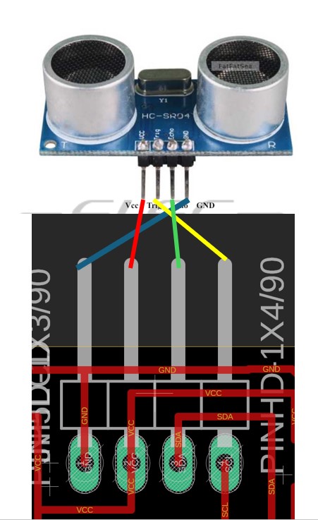
The code below is for Ultrasonic Sensor. It attempts to send a signal controlled by TrigPin 6 and it detects the duration it takes to recieve the signal using input pin 7. It is commonly taught in science for physics echo. The code have comments that explains to mty best of abilities
#include <Arduino.h>

    // Define the connections to the HC-SR04
    const int trigPin = 6  ; // SCL;
    const int echoPin = 7  ; // SDA;

    void setup() {
        // Initialize Serial Monitor
        Serial.begin(9600);

        // Configure the trigger and echo pins
        pinMode(trigPin, OUTPUT);
        pinMode(echoPin, INPUT);
    }

    void loop() {
        // Ensure the trigger pin is set low
        digitalWrite(trigPin, LOW);
        delayMicroseconds(2);

        // Trigger the sensor by setting the trigPin high for 10 microseconds
        digitalWrite(trigPin, HIGH);
        delayMicroseconds(10);
        digitalWrite(trigPin, LOW);

        // Read the echoPin, returns the sound wave travel time in microseconds
        long duration = pulseIn(echoPin, HIGH);

        // Calculate the distance
        long distance = duration * 0.034 / 2; // Speed of sound wave divided by 2 (go and return)

        // Display the distance on the Serial Monitor
        Serial.print("Distance: ");
        Serial.print(distance);
        Serial.println(" cm");

        // Delay a short period of time to ensure accurate readings
        delay(500);
    }
Challenges I Encountered and My Solutions
What was challenging was I had to ensure the input and output devices are using same microcontroller as my final project so i had to redo this section.
Below is the recording of what i previously did with ATTINY1614 for input devices. Hmmm What was challenging this week, I guess is I redo the projects so many times, while managing life priorities, but the i saved the file names and link wrongly and also saved the files into differenbt git folders (i reported that my folder couldnt push to git so i clone to new folder but I made amendments in old folder and taught I saved properly.) hence causing alot of issues to my marker/instructor..
I really like to thank my Instructor for the help and accomodation, I had been so messy (i redid this project doc in both html and mkdoc, and many different folders and versions of codes. I get really scared when assignments are challenged so i will take some time to look through again. and keep forgetting to put in pictures and codes. ) and I really want to try and master the different things so I really took alot of times previously so that I can learn more.. Below is a sample of what I did prior esp32.
Also the original video, the serial monitor words were too small and unclear. so took instructor advise to redo.
Original Design Files and Source Code
- Source Code for ESP32 - Source Code for ATTINY1614 the older project i did - ESP32C3 Board Designed
Hero Shot of My Board
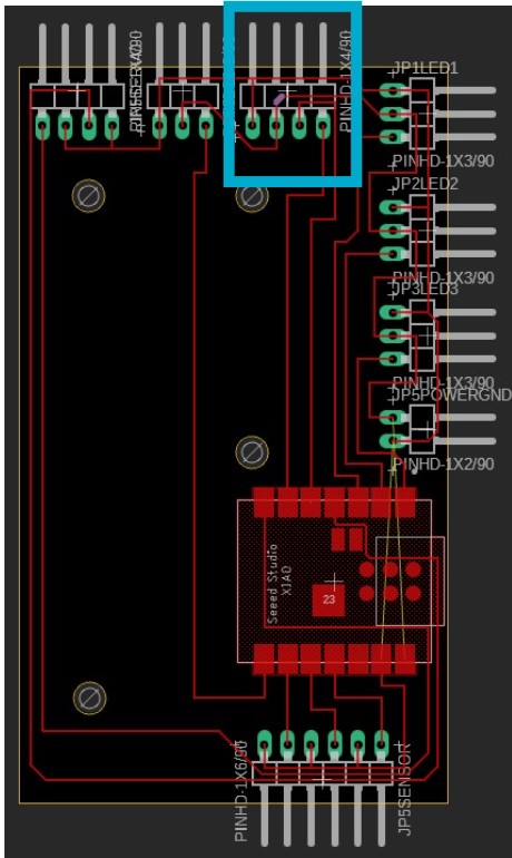
Below is a 'hero shot'. Hope this time ESP32 is sufficiently done! Honestly I think i have a messy table also. I adjusted the font of the serial monitor so that video is clearer
Understanding Input Methods in Electronic Systems
Effective interaction with the external environment is crucial for electronic systems, achieved through various input methods and components. This section delves into ports, comparators, A/D converters, and I2C communication, explaining their functions and applications.
| Input Method/Component | Description | Applications |
|---|---|---|
| Ports | Physical interface points on microcontrollers used to connect external devices and sensors. | Used for digital and analog signal inputs, allowing microcontrollers to read data from switches, sensors, and other input devices. |
| Comparator | An electronic component that compares two voltages and outputs a digital signal indicating the higher voltage. | Commonly used in applications requiring threshold detection, such as battery level indicators and light sensors. |
| A/D (Analog-to-Digital Converter) | Converts analog signals into digital data that microcontrollers can process. | Essential for applications involving analog sensors, such as temperature or light intensity measurements, allowing digital systems to interpret analog inputs. |
| I2C (Inter-Integrated Circuit) | A serial communication protocol that uses two wires (SDA for data, SCL for clock) to connect multiple devices. | Enables communication between microcontroller and various peripherals like displays, sensors, and other ICs with minimal wiring, facilitating complex data exchange in a multi-device setup. |